Chapter 8. Safety Analysis for LOCAs
In a short summary, what is done during Design Certification & plant licensing is a Safety Analysis Report. The NRC licensing requirements postulate Design Basis Accidents, and the Reactor designers run sophisticated computer code analysis using the reactor coolant system/core math models to predict plant thermo-hydraulic response to solve for (in case of LOCA) the peak fuel rod cladding temperature. The limit is 2200F (by law); which leaves a significant safety margin to the on-set of the dreaded zirconium-water reaction (Zr-H2O) which gets really accelerated about 2800F. The fuel rod are ~1/2" diameter zircalloy tubes (the cladding), filled with ceramic fuel pellets about an inch tall each. The clad is the first barrier to fission product release from the fuel itself. At ~2800F high temperature zircalloy in contact with water (steam) undergoes a rapid oxidation chemical reaction which is exothermic (gives off heat) so it "runs away" once it starts and in the process it releases free hydrogen gas, leaving the clad chemically changed to a brittle flimsy zirc-oxide metal. The free hydrogen gas is a problem because when it is mixed in the right concentration with oxygen it is explosive. Thus the goal of the Safety Analysis calculation is to show that the Emergency Core Cooling Systems respond quickly enough to keep the fuel cladding cooled below the 2200F limit, providing a safety margin to the onset of the zirc-water reaction. The LOCA analysis actual worst break location (for peak clad temperature) is a 26" Cold Leg break. That is not obvious, but it is worse than the 36" Hot Leg break because in a Hot Leg break all the break flow is through the core first and then to the hole, so the core never empties of water which would leave, the fuel without a cooling medium. But in a Cold Leg break all the flow is backwards through the core towards the hole, thus you get a "blow-down" phase, followed by "re-flood" phase (with the ECCS pumps), followed by "re-fill" phase (up to the hole location elevation). If you remember the system drawing from part 1, High Pressure Injection, LPI, and even the Core Flood tanks are all dumping into the inlet side of the reactor pressure vessel. So when a Cold Leg ruptures and the Reactor Coolant System depressurizes virtually all the hot water in the system wants to “flash” to steam, and everything the ECCS is initially injecting is rushing to the hole location. So for a time the core is only surrounded by some steam for heat removal. A Hot Leg break has no blow-down or re-flood phase because the core never empties. Thus the Cold Leg break is worst case for a fuel rod peak clad temp.
Analysts for these LOCA accidents assume what is called a guillotine rupture with lateral displacement of the pipe so unrestricted flow occurs from both sides of the break and also one single active or passive equipment failure too (that's why there's 2 of everything). So a hot leg break is a 14.1 ft-sq hole, a cold leg break is a 7.4 ft-sq hole, etc. (these numbers won't be on the test). Then they do "sensitivity" studies with every pipe size penetrating the reactor coolant system. Bottom line, if peak clad temperature during the break is below 2200F, you're A-OK. These analyses are accurate, backed up by actual scale model tests at National Labs (well at least now, early ‘70s data from what was called the LOFT experiments [Loss of Fluid Test] was showing all the initial assumptions on LOCA “blow-down, re-flood, and re-fill were wrong such that the cladding temperature limit would be exceeded for LOCAs. That made the old Atomic Energy Commission (AEC) so nervous they attempted to hide it while they figured out how to deal with it. The end result was better modeling, more testing, and basically redesign of nuke fuel to lower the fuel rod power densities so they could pass the tests. This “scandal” was one of the things that led to the demise of the old AEC) These analyst guys can tell you the mass of water in the system, core vessel, break flow, pressure, temp, etc. at ~1/10 sec intervals for the duration of the event. For a comparison the equivalent hole size for the stuck open PORV at TMI (which drained the system) is 0.007 ft-sq. Yup, how's that grab you? A double-o-seven hole melted their core. At this point, analytically, they say if we can handle the big ones, obviously we'll be OK on the smaller ones. In the Kemeny Commission Report, Report from the Technical Assessment Task Force, Vol. I, it states:
“The design of the emergency core cooling system is based on the ability to keep the core covered under serious accidents postulated to be caused by ruptures that might occur in the reactor coolant system pressure boundary. The system design is analyzed to show that it is adequate to pgrform (sic) its function for a wide range of break sizes from about 0.04 ft up to and including a 14.1 ft split in the reactor coolant system hot leg.”
Thus it appears that the 0.007 ft-sq PORV hole size was not specifically analyzed.
After the effect on the reactor core is determined, analysts next look at the total energy and fission product dump into the Containment Vessel due to the leak. The Containment will pressurize due to just the steam alone, but also due to the steam heating the air in the vessel. Again, system modeling and computer calculations are done considering the functioning of additional systems engineered to suppress this Containment pressurization and temperature increase. These systems are the Containment (water) Spray System and the Containment Air Coolers. The success criteria for this analysis are that the Containment Vessel design pressure and design temperature are not exceeded due to the energy dump into the vessel from the LOCA.
Finally the calculated fission product release into the Containment Vessel is analyzed with respect to an assumed vessel leakage rate using an assumed vessel pressure equal to design pressure. This results in a calculated radiation release to the environment. Sophisticated meteorological condition computer modeling is used to predict a release plume pathway considering wind speed, direction, possible temperature inversions, plume dispersion, etc. to develop a plume arc. The potential radiation dose to people outside the plant control boundary (in unrestricted access areas) is calculated. That dose is evaluated against predetermined limits.
What can be seen here is for this one discussed event, a Loss of Coolant Accident, first the effect on the reactor core is analyzed, then the effect on the Containment Vessel from that core damaged is analyzed, and finally the off-site radiation dose to the general public from that event is analyzed. At each step specific acceptance criteria must be met. Further, in all analyses, what is known as “worst case” input assumptions are used. This means, for example, if the gauge used to read the Reactor power can read 100% power when the event starts, but the actual power is 112% due to gauge errors, the analysis will use 112% power as the starting point. In addition they input every parameter that may affect the results in the worse case direction, all at the same time. This information is hardly kept secret. If you live anywhere relatively close to a US nuclear power plant, a local public library will have the plant updated, revised Safety Evaluation Report available for public review.
Every postulated event, or Design Basis Accident (DBA) had an analysis; Loss of Coolant Accident, Steam Generator Tube Rupture, Load Rejection, Turbine Trip, Loss of Feedwater, Cold Water Accident (RCP problems), Fuel Handling Accident, etc. And in turn each of those had a Single Event Emergency Operating Procedure (EOP) to cope with it. The procedure steps mainly focused around the equipment used in the analysis, e.g. operator verifications of automatic equipment actions or manual actions needed to cope with the analyzed event. Failures never cascaded, other than the design basis required “single failure”, like one of the two installed pumps failed to start. Then you can add in EOPs for any normal large-sized industrial power plant expected event like a Loss of Condenser Vacuum, a Condenser Cooling Water Pump Failure, or perhaps an Electrical Distribution Bus trip. Utilities have been running power plants long before the age of nuclear reactors, so they know things can happen. Operators were required to memorize all the Immediate Operator Action steps of all of these EOPs. You don't have to like this approach; it's how it was done then.
So What’s the Odds?
Over a beer, that’s what most folks want to know. Actually there is now a process that is used by the industry and the regulator to look at such things. It’s called Probabilistic Risk Assessment (PRA). This hardly my area of expertise but it’s another math model thing. But it is backed up by real data when available, e.g. known hardware failure rates, operating experience reports, etc. A good general discussion is available at this web site link: PRA INFO. Probabilistic Risk Assessment is hardly a new idea as it was first introduced in the nuke industry in 1975 as a document called the Rasmussen Report or WASH-1400. If you read the linked reference you can see it can be a useful tool for both nuke plant organizations and regulators.
Typical PWR Fuel Assembly
A typical B&W reactor has 177 fuel assemblies, loaded in a roughly circular array. A single fuel assembly looks like this:
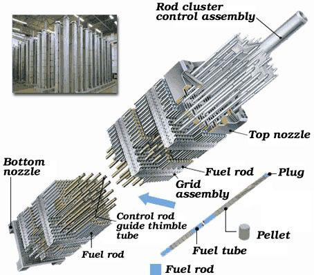
They are built in a 15X15 fuel rod array, but there are 16 blank locations to accept the control rod fingers, and a center blank for an "in-core" thermocouple instrument. Thus there are 208 fuel rods per fuel assembly. Each fuel rod is loaded with the U-oxide pellets, a top spring spacer, and pressurized to ~400PSI with Helium gas. The Helium gas increases the heat transfer coefficient across the empty "gap" volume between the fuel pellets and clad inside wall. During operation the pellets undergo densification (they shrink), in fact some can crack and fracture, the spring keeps the stack together eliminating empty space (which could cause local power density anomalies). The densification effect has to be accounted for in the design, because what it does is actually increase the power density locally (more fuel in a smaller volume) which tends to increase the centerline fuel temperature as the rod ages. The "gap" ends up holding all the fission product gasses, Xenon, Krypton, Argon, etc. (they migrate out to the gap volume). This effect is important because when fuel starts to fail during Zr-water reactions (generally from the top down as the core water uncovers the fuel ), as soon as the first clad breach occurs all the fission product gasses in that fuel pin dump into the coolant stream. This is followed closely by all the volatile fission products (like Iodine) as the core fuel heat increases. If the initial cause was a coolant system breach (like TMI) basically all the core fission gas and volatile fission products end up inside the primary containment vessel. The ceramic pellets will start to melt ~5000F and start slumping to the bottom of the reactor pressure vessel.
After TMI was disassembled it was learned some strange stuff can go on. They found eutectic metals, where 2 dissimilar metals in contact melt at a lower melting point than either alone. This was somewhat unsuspected as some of the reactor internals did not reach the theoretical melting point for that metal. This means the whole slop pile in the bottom of the reactor vessel is a combination of fuel, spacer grids, control rod material, upper & lower core alignment grids, etc. If it stays there it remains a cool-able geometry. And it doesn’t have “critical mass” geometry so the reactor slop pile can’t really “run” in the sense of having a self sustained fission chain reaction. Another unexpected component behavior was the response of some of the in-core thermocouples. A thermocouple is simply 2 dissimilar metals in contact with each other at one end. When heated a voltage is induced across the other end of the 2 wires, which will change as the temperature changes, and can be measured with a voltmeter. Each individual thermocouple can then be field calibrated by the manufacturer to supply a calibration curve for each one, and a corresponding temperature versus voltage curve is supplied. When these are hooked to a temperature meter in the plant, and each voltage is adjusted for its calibration curve, they read the temperature at their core location. When these instruments are inserted up through the bottom of the Reactor Pressure Vessel and into the center of a fuel assembly, they pretty much read the fuel temperature at that location. During the TMI accident these instrument read-outs were looked at and some of them read 2000F, the limit of their indicated range. The readings were considered as being impossible. When the core fuel assemblies began to melt down from the top, some of the in-core thermocouples also started to melt. In some cases the two shorter wires maintained contact with each other such that a voltage was still present at the other end of the wire. Of course the thermocouple was now off its calibration curve, so its raw temperature reading was not accurate. However its ability to show a trend, either up or down, still worked. This information became useful in future Severe Accident Management Guidelines.
Three Mile Island Accident Core End State
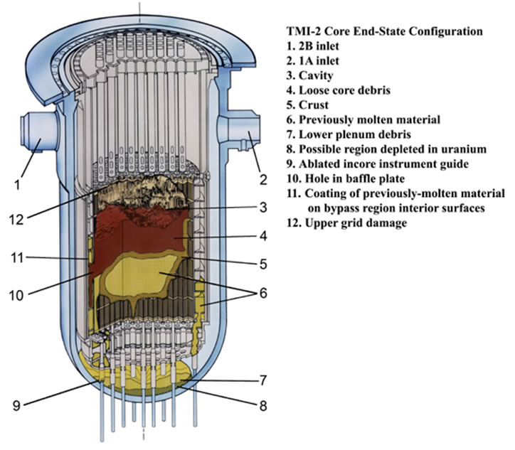
Note at item 9 an in-core instrument guide tube is ablated (gone). These tubes guide the in-core instrument wire up into a fuel assembly at the proper location when the wire is inserted from a remote location through the other end of the guide tube. This is a potential pathway for melted fuel out of the Reactor Pressure Vessel and into the guide tube. However the guide tube itself is still part of the system pressure boundary, so even if melted fuel is flowing into the guide tube it is not dripping onto the Containment Vessel floor under the Reactor Pressure Vessel. At the Davis Besse plant this area under the Pressure Vessel is called the Containment Normal Sump, and it caught all the PORV leakage from our September ’77 event. And it stayed there because the same signal that actuates the Emergency Core Cooling Systems also closes this sump pump discharge valve flow path out of Containment Vessel.